• Home

    • Welcome to the next step of Collaboration within the Cisco technical community in Belgium and Luxembourg
  • Categories

  • Archives

  • Cisco Belgium Tweets

Cisco Performance Routing (PfR) example

Performance Routing (PfR) complements traditional routing technologies by using the intelligence of a Cisco IOS infrastructure to improve application performance and availability. PfR can select the best path for each application based upon advanced criteria such as, reachability, delay, loss, jitter, and mean opinion score (MOS).

PfR can also improve application availability by dynamically routing around network problems like black holes and brownouts that traditional IP routing may not detect. In addition, the intelligent load balancing capability of PfR can optimize path selection based on link use or circuit pricing.

Some of the scenario’s you could create are described on below links

Enterprise Intranet Solutions:

Internet Edge Solutions:

In this example we will demonstrate the rerouting of a Cisco Video IP Phone traffic based on Jitter criteria.

The setup is as follows:

PfrLabexample1

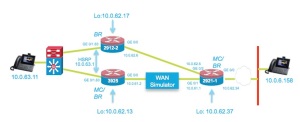
We use the ip sla functions of the router  to verify the jitter behaviour of a WAN link between the 3925 and 2921-1 router.
As soon as the Jitter goes above a threshold the Voice/Video Traffic will be rerouted to an alternative link.
(Note: that you could allow all other traffic on the degraded link)
The following video shows the effect of Jitter on the phone,  and the reaction off Pfr (timing can be tuned of course).
.
.
As mentioned in the video, you’ll see a change in routing behaveour, as example we’ll take the output off router 2921-1:
-Sep  3 17:16:19.358: %PFR_MC-5-ROUTE_EVENT: 50% of traffic classes controlled through policy VIDEO_VOICE 10 are NOT INPOLICY (trigger-log-percentage is 30%)
-Sep  3 17:17:19.382: %PFR_MC-5-ROUTE_EVENT: 100% of traffic classes controlled through policy VIDEO_VOICE 10 are INPOLICY (trigger-log-percentage is 30%)
-Sep  3 17:17:49.302: %PFR_MC-6-OOP_ACTIVE_MODE: Relative short term delay measurement is out of policy. Appl Prefix 10.0.63.11/32 N    17 [16384, 65535] [16384, 65535], delay 13, BR 10.0.62.34, i/f Gi0/1relative change 225, prev BR Unknown i/f Unknown
-Sep  3 17:17:49.502: %PFR_MC-6-ROUTE_EVENT_INFO: Appl Prefix 10.0.63.11/32 N    17 [16384, 65535] [16384, 65535]: route changed to BR 10.0.62.34, i/f Gi0/2, due to Jitter criteria. Out of policy reason: delay criteria
<-  A route is injected in router 2921-1 for the IP Phone .11 (PBR)
Below you can find the key commands to configure above setup and some show commands to illustrate.
.
For additional examples do have a look at:

Cisco 3925 ISRG2:

!
key chain key1    
<- For secure communication between master & border
 key 1
  key-string cisco
!
pfr master
 policy-rules VIDEO_VOICE
<- Defined specific rules for a specific application
 logging
 !
 border 10.0.62.13 key-chain key1
  interface GigabitEthernet0/0 external
   link-group primary
<- Definition of the link- group, could be any name, linked to the pfr maps
  interface GigabitEthernet0/1.63 internal
 !
 border 10.0.62.17 key-chain key1
  interface GigabitEthernet0/0 external
   link-group secondary
  interface GigabitEthernet0/1.63 internal
 !
 no learn                                                                  
<- Learning disabled
 !
!
pfr border
 local Loopback1
 master 10.0.62.13 key-chain key1
 active-probe address source interface Loopback1
!
!
!
interface Loopback1
 ip address 10.0.62.13 255.255.255.252
!
interface GigabitEthernet0/0
 ip address 10.0.61.2 255.255.255.240
 duplex auto
 speed auto
!
interface GigabitEthernet0/1
 no ip address
 duplex auto
 speed auto
!
interface GigabitEthernet0/1.63
 encapsulation dot1Q 63
 ip address 10.0.63.3 255.255.255.0
 standby 1 ip 10.0.63.1
 standby 1 priority 150
 standby 1 preempt
!
!
interface GigabitEthernet1/0
 ip address 10.0.62.45 255.255.255.252
!
!
router eigrp 1
 network 10.0.61.0 0.0.0.15
….
!
router bgp 65002
 bgp log-neighbor-changes
 neighbor 192.168.0.2 remote-as 65001
 !
 address-family ipv4
  network 10.0.63.0 mask 255.255.255.0
  neighbor 192.168.0.2 activate
 exit-address-family
!
!
ip access-list extended VOICE_VIDEO_ACCESS_LIST
 permit udp any range 16384 65535 host 10.0.6.155 range 16384 65535
 permit udp any range 16384 65535 host 10.0.6.158 range 16384 65535
!
ip sla auto discovery
ip sla responder     
<- IP SLA responder as well , to respond to probes of 2921-1
ip sla enable reaction-alerts
!
!
!
pfr-map VIDEO_VOICE 10
 match traffic-class access-list VOICE_VIDEO_ACCESS_LIST
<- Match Voice & Video traffic
 set mode monitor fast
<- Fast failover choosen
 set resolve jitter priority 1 variance 5
 set resolve delay priority 2 variance 50
 set resolve loss priority 3 variance 50
 set jitter threshold 100
 set active-probe jitter 10.0.62.34 target-port 3050
<- Active Jitter Probe
 set probe frequency 5
 set link-group primary fallback secondary
<- link group fallback (primary and secondary can be any name)
!
control-plane
!
.

The 2921-2 Border Router 

.
….
key chain key1
 key 1
  key-string cisco
!
!
!
pfr border
 local Loopback1
 master 10.0.62.13 key-chain key1
 active-probe address source interface Loopback1
<- Used loopback as source for the Jitter probe packets
!
interface Loopback1
 ip address 10.0.62.17 255.255.255.252
!
!
interface GigabitEthernet0/0
 description WAN interface
 ip address 10.0.62.6 255.255.255.252
 duplex auto
 speed auto
!
interface GigabitEthernet0/1
 no ip address
 duplex auto
 speed auto
!
interface GigabitEthernet0/1.63
 encapsulation dot1Q 63
 ip address 10.0.63.2 255.255.255.0
 standby 1 ip 10.0.63.1
 standby 1 preempt
!
router eigrp 1
 network 10.0.62.4 0.0.0.3
We do a show command off the Master Controller before change of jitter:
3925#  sho pfr master
OER state: ENABLED and ACTIVE
  Conn Status: SUCCESS, PORT: 3949
  Version: 3.3
  Number of Border routers: 2
<- Master controls 2 border routers
  Number of Exits: 2
  Number of monitored prefixes: 4 (max 5000)
  Max prefixes: total 5000 learn 2500
  Prefix count: total 4, learn 0, cfg 4
  PBR Requirements met
  Nbar Status: Inactive
Border           Status                UP/DOWN             AuthFail  Version  DOWN Reason           <- Both Border routers are active
10.0.62.17       ACTIVE                UP       1w5d          0  3.3
10.0.62.13       ACTIVE                UP       1w5d          0  3.3
….
Default Policy Settings:
  backoff 90 900 90
  delay relative 50
  holddown 90
  periodic 90
  probe frequency 56
  number of jitter probe packets 100
  mode route control
  mode monitor both
  loss relative 10
  jitter threshold 1000
  mos threshold 3.60 percent 30
  unreachable relative 50
  trigger-log percentage 30
Learn Settings:
  current state : DISABLED
<-  We disabled learning in this example, going for fast failover
….
We’ll now look at the traffic-classes defined, seen we disabled
learning and enabled only 1 application prefixed (Voice/Video)
(only 2 traffic-class are defined).
One could use Netflow or NBAR2 to profile traffic.
c3925H#sho pfr master traffic-class
OER Prefix Statistics:
 Pas – Passive, Act – Active, S – Short term, L – Long term, Dly – Delay (ms),
 P – Percentage below threshold, Jit – Jitter (ms),
 MOS – Mean Opinion Score
 Los – Packet Loss (percent/10000), Un – Unreachable (flows-per-million),
 E – Egress, I – Ingress, Bw – Bandwidth (kbps), N – Not applicable
 U – unknown, * – uncontrolled, + – control more specific, @ – active probe all
 # – Prefix monitor mode is Special, & – Blackholed Prefix
 % – Force Next-Hop, ^ – Prefix is denied
DstPrefix           Appl_ID Dscp Prot     SrcPort     DstPort SrcPrefix
           Flags             State     Time            CurrBR  CurrI/F Protocol
         PasSDly  PasLDly   PasSUn   PasLUn  PasSLos  PasLLos      EBw      IBw
         ActSDly  ActLDly   ActSUn   ActLUn  ActSJit  ActPMOS  ActSLos  ActLLos
——————————————————————————–
10.0.6.155/32             N    N  udp 16384-65535 16384-65535 0.0.0.0/0
                          INPOLICY       @6        10.0.62.13 Gi0/0           PBR
               U        U        0        0        0        0        0        0
               2        2        0        0        0        0        0        0
10.0.6.158/32             N    N  udp 16384-65535 16384-65535 0.0.0.0/0
                          INPOLICY      @37        10.0.62.13 Gi0/0           PBR
<– Detected application, in policy exiting GE 0/0
               U        U        0        0        0        0      178      178
               2        2        0        0        0        0        0        0
The active probe:
sho pfr master active-probes forced:
        OER Master Controller active-probes
Border   = Border Router running this Probe
Policy   = Forced target is configure under this policy
Type     = Probe Type
Target   = Target Address
TPort    = Target Port
N – Not applicable
The following Forced Probes are running:
Border          State    Policy             Type     Target          TPort Dscp
10.0.62.17      ACTIVE   10                 jitter   10.0.62.34       3050 defa
10.0.62.13      ACTIVE   10                 jitter   10.0.62.34       3050 defa
After the rerouting off the traffic. Use a other sho command to illustrate on the 3925:

sho pfr master traffic-class performance

=============================================================

…..

Traffic-class:

Destination Prefix : 10.0.6.158/32           Source Prefix    : 0.0.0.0/0

Destination Port   : 16384-65535             Source Port      : 16384-65535

DSCP               : N                       Protocol         : udp

Application Name:  : N/A

General:

Control State                   : Controlled using PBR

Traffic-class status            : INPOLICY

Current Exit                    : BR 10.0.62.17 interface Gi0/0, Tie breaker was None

Time on current exit            : 0d 0:8:2

Time remaining in current state : @59 seconds

Traffic-class type              : Configured

Improper config                 : None

Last Out-of-Policy event:

No Out-of-Policy Event

Average Passive Performance Current Exit: (Average for last 5 minutes)

Unreachable            : 0% — Threshold: 50%

Delay                  : 0% — Threshold: 50%

Loss                   : 0% — Threshold: 10%

Egress BW              : 1033 kbps

Ingress BW             : 1030 kbps

Time since last update : 0d 0:0:28

Average Active Performance Current Exit: (Average for last 5 minutes)

Unreachable            : 0% — Threshold: 50%

Jitter                 : 0 msec — Threshold: 10000 msec

Delay                  : 80% — Threshold: 50%

Loss                   : 0% — Threshold: 10%

Last Resolver Decision:

BR              Interface    Status       Reason       Performance Threshold

————— ———— ———— ———— ———– ———

10.0.62.13      Gi0/0        Eliminated   Jitter       N/A          N/A     

   10.0.62.17      Gi0/0        Best Exit    Jitter       N/A          N/A   

.

The Central router 2921-1

.
(has also pfr enabled)
!
!
key chain key2
 key 1
  key-string cisco
!
!
pfr master
 policy-rules VIDEO_VOICE
 logging
 !
 border 10.0.62.34 key-chain key2                            
<- Only 1 border router this time, with 2 external interfaces
  interface GigabitEthernet0/2 external
   link-group secondary
  interface GigabitEthernet0/1 external
   max-xmit-utilization percentage 100
   link-group primary
  interface GigabitEthernet0/0 internal
 !
 no learn
!
pfr border
 local GigabitEthernet0/0
 master 10.0.62.34 key-chain key2
!
!
interface Loopback0
 ip address 10.0.62.37 255.255.255.252
!
interface GigabitEthernet0/0
 ip address 10.0.62.34 255.255.255.252
 duplex full
 speed 1000
!
interface GigabitEthernet0/1
 ip address 10.0.61.1 255.255.255.240
 duplex auto
 speed auto
!
interface GigabitEthernet0/2
 ip address 10.0.62.5 255.255.255.252
 delay 20
 duplex auto
 speed auto
!
!
router eigrp 1
 network 10.0.61.0 0.0.0.15
….
!
!
ip access-list extended VOICE_VIDEO_ACCESS_LIST
 permit udp any range 16384 65535 host 10.0.63.11 range 16384 65535
!
ip sla auto discovery
ip sla responder
ip sla enable reaction-alerts
!
!
!
pfr-map VIDEO_VOICE 10
 match traffic-class access-list VOICE_VIDEO_ACCESS_LIST
<- This time ip phone .11
 set mode route control
 set mode monitor fast
 set resolve jitter priority 1 variance 5
 set resolve delay priority 2 variance 50
 set resolve loss priority 3 variance 50
 set jitter threshold 120
 set active-probe jitter 10.0.63.1 target-port 3050
 set probe frequency 5
 set link-group primary fallback secondary
!
Have fun!
 Johan De Ridder

Software Defined networking (SDN) – Segment routing

In the IP NGN part of the networking world, service providers, large enterprise, public customers running MPLS networks today are striving towards cost reduction while increasing service velocity.

Two domains come to the surface in order to achieve these goals :

  • network simplification
  • creation of flexible service infrastructure

There are various components which come into play in each domain, and some have hooks in both.  We will cover multiple components in the upcoming SP technical blogs.

The one innovative piece we’ll cover in this blog is called segment routing.  Segment routing (SR) is coming to a conclusion in the IETF and is clearly playing in the ‘network simplification’ domain, however, segment routing also opens up opportunities to benefit from Cisco’s SDN orchestration technology which is also known as ‘Open Network Environment’ (ONE).

To quote the IETF draft :

segment routing

segment routing

It is simple to deploy and operate as it removes the need for any signalling state in the network (i.e. RSVP-TE)  for explicit paths (i.e. for traffic engineering).  The state is no longer in the network, but in the packet.

The forwarding state (aka segment) is established by the IGP, which can be ISIS or OSPF and is agnostic to forwarding dataplane ; which can be IPv6 or MPLS.

The benefits of SR include :

  • automated and guaranteed Fast ReRoute (FRR)
  • An SR core router scales much better than with RSVP-TE
    – The state is not in the router but in the packet
    – N+A vs N^2 (N= #nodes ; A= #adjacencies)
  • CoS based TE
  • full control and OAM
  • The network is simple, highly programmable and responsive to rapid changes
    – perfect support for centralized optimization efficiency, if required

In the following video, Clarence provides some more info on SR :

And the following SP360 blog also covers segment routing :

http://blogs.cisco.com/sp/segment-routing-impact-on-software-defined-networks/

Cisco Connect

Friendly reminder don’t forget to come to Cisco Connect Belgium !

ciscoconnect

To Register:

http://www.cisco.com/web/europe/ciscoconnect2013/index_be.html

Welcome to Cisco Connect 2013

Cisco Connect will happen on Thursday April 18 2013 in Kinepolis Imagibraine in Braine-L’Alleud and it promises to be a unique experience.  It will be an interactive event with 10 North-European countries ‘connected’ in realtime.

We will offer you a very appealing program with inspiring keynote speakers such as Pieter Timmermans, CEO, Carlos Dominguez, Senior Vice President Cisco, Andy Butler, Distinguished Analyst, Gartner who will bring their ideas and experience live and- or virtually.

The agenda holds several keynote- and breakout sessions by Cisco Experts, Intel® and Platinum Sponsors.  Besides, you will also find a large exhibition area with Cisco partners showing their added value.  Off course we would like you also to take the time for expanding your network with your peers in industry.

Looking forward to meet you at Cisco Connect 2013!

Kindest regards,

Pol Vanbiervliet
Managing Director
Cisco Belgium & Luxembourg
Intel® is Official Sponsor for Cisco Connect 2013

Cisco Jabber for Windows plugin twitter

Hi All,

If you would like to show up your twitter messages (or other applications) as a plugin in Jabber Client please do the following:

CaptureJabberoverview

Instructions:
  1. On a Windows 7 machine, go to the directory: C:\Users\%userprofile%\AppData\Roaming\Cisco\Unified Communications\Jabber\CSF\Config   (best is you do a search in your windows for jabber-config-user.xml)
  2. edit the jabber-config-user.xml file in wordpad (save as text file with extension xml).
Working config:
<?xml version=”1.0″ encoding=”utf-8″?>
   <config version=”1.0″>
    <Client>
        <jabber-plugin-config>
            <browser-plugin>
<page refresh=”true” preload=”false”>
                     <tooltip>twitter</tooltip>
                    <url>https://mobile.twitter.com/</url>
                </page>
          </browser-plugin>
        </jabber-plugin-config>
    </Client>
       </config>
                  3.  Save the file and ensure its still called jabber-config-user.xml
                  4. restart jabber
It is possible to add multiple applications in the TAB,  for example if you would like to add in linkedin you slide the following after the  </page> :
<page refresh=”true” preload=”false”>
     <tooltip>linkedin</tooltip>
     <url>http://touch.www.linkedin.com/</url&gt;
</page>
For info on Jabber goto http://www.cisco.com/go/jabber
Have fun,
Johan

CiscoLive 2013 in London is ready to start

The biggest European Cisco event of the year – CiscoLive – is ready to start!!

As from tomorrow the techtorials are starting, followed as from Tuesday by the Keynotes and the general sessions. We look forward to meet the numerous Belgian and Luxemburg customers and partners attending the event. To give you already a glimpse of one of the main content tracks, please see underneath banner !

unified access ciscolive 2013

For those not able to attend physically CiscoLive in London, do not hesitate to register on the virtual event web site, where you will be able to see the keynotes and get access to very interesting event content : http://www.ciscolive.com/london/virtual/

CiscoLive 2013 – Jan 28 – Feb 1st 2013, London, UK

UC virtualization – Co-residency of 3rd party apps with Cisco UC VMs is now supported!

Customers have been asking for co-residency of 3rd party non-UC applications on the same VMware host / physical server with our UC apps for a very long time. Virtualization has matured, and is common practice in any IT organization. Although it still makes sense to “isolate” virtualized UC applications on dedicated hardware, customers now get the flexibility to mix and match our applications and 3rd party as they prefer. The server industry, including our own UCS portfolio, can nowadays scale servers to 10s of CPU cores, hundreds of gigabytes of RAM and virtually unlimited storage capacity. Customers wanting to maximize and optimize resource utilization and consolidate many servers to limit the server hardware footprint and cost of operation can now also include our UC apps in there…

Not sure if the example is relevant, but basically this means that a customer can now run Cisco Unified Communications Manager, file and print services and a mail server on the same box / VMware host.

The biggest challenge for Cisco was how to guarantee that our apps would get the required resources when they are co-located with others on the same physical server. Getting it working is one, but how can you define a design that you can actually fully support while there are so many things outside of your control… It’s possible,

All relevant details can be found on the following url:

http://docwiki.cisco.com/wiki/Unified_Communications_Virtualization_Sizing_Guidelines#General_Rules_for_Co-residency_and_Physical.2FVirtual_Hardware_Sizing  (see topic 2.2)

In summary, this is a short overview of the rules we have set forward for “full co-residency”:

-UC on UCS rules apply with 3rd party VMs (no oversubscription for vCPU, vRAM, vDisks, etc…)

– Not allowed with BE6k

– Not allowed with Cisco UC Virtualization Foundation or Cisco UC Virtualization Hypervisor

– Cisco cannot guarantee the VMs will never starved for resources. If this occurs, Cisco could require to power off or relocated all 3rd party applications

TAC has defined the criteria that need to be met to get their support in an application note that can be found at:

http://www.cisco.com/en/US/products/ps6884/products_tech_note09186a0080bbd913.shtml

Normalization scripting for SIP Trunking first step

SIP trunks can connect to a variety of endpoints, including PBXs, gateways, and service providers. Each of these endpoints implements the SIP protocol a bit differently, causing a unique set of interoperability issues. To normalize messages per trunk, Cisco Unified Communications Manager allows you to add or update scripts to the system and then associate them with one or more SIP trunks.

The normalization scripts that you create allow you to preserve, remove, or change the contents of any SIP headers or content bodies, known or unknown. After you configure a normalization script in Cisco Unified Communications Manager, you associate the script with a SIP trunk by configuring the Normalization Script fields in the Trunk Configuration window

The language used is Lua it is an open source, lightweight scripting language.

For info on Lua see http://www.lua.org/

As a practical example we change in the SIP invite for a outgoing call on a sip trunk, the IP destination addresses in the SIP URI to a domain name.

From: 

INVITE sip:+3227784342@1.1.1.10:5060 SIP/2.0

The normalization script:

M = {}

function M.outbound_INVITE(msg)

local method, ruri, ver = msg:getRequestLine()

local uri = string.gsub (ruri, “1.1.1.10”, “domain1.a.be”)

msg:setRequestUri(uri)

end

return M

Changes into:

INVITE sip:+3227784200@domain1.a.be:5060 SIP/2.0

For some more info see:

http://developer.cisco.com/web/sip/home

http://www.cisco.com/en/US/docs/voice_ip_comm/cucm/admin/8_6_1/ccmcfg/b06scrpt.html#wpxref92424

Some very good thoughts about Why should you care about Cisco UCS

Folks,

I wanted to share a few very good articles and web documents coming from friends into one condensed updated post about all the great things that Cisco UCS can provide to your organization :

Last performances update about our solution :

In the three years since its introduction, Cisco Unified Computing System™ (Cisco UCS™) powered by Intel® Xeon® processors captured 63 world performance records,UCS and Intel Xeon Processors: so, please check this out : 63 World-Record Performance Results

In response to what skeptics were saying 3 years ago :

Cisco as a server vendor! Ha!

Remember back when the company first unveiled its “Unified Computing System” (UCS)? At the time, the thought of Cisco being in the server market seemed almost laughable. But, this was a journey that we had seen before. Similar guffawing was heard when Cisco jumped into the voice market. Way back in the day, when I was in internal IT, Cisco acquired its way into the VoIP market and rode the IP wave to market leadership in only about a decade. When you think about how, historically, extremely difficult voice share was to gain, the fact that Cisco managed to grab as much share as it did, and as fast as it did, was remarkable…

more to read, here…

Some good tips to bear in mind if you want to do an apples to apples cost comparison ?

…therefore evaluate the real cost of implementing Cisco UCS solutions

The Service-Profile concept :

In this post Marcel will try to explain what a service profile template is within Cisco UCS. However to start with the basics let’s start with a service profile. I assume you are aware of the Cisco UCS Emulator. if not you can download it from here using your CCO account: http://developer.cisco.com/web/unifiedcomputing/home

So what is a service profile within Cisco UCS?
A service profile defines a single server and its storage and networking characteristics and are stored in the Cisco UCS Fabric Interconnects. Each server connected to the Fabric Interconnects are specified with a service profile. The advantage of service profiles are mainly automation of your physical hardware configuration like BIOS settings, firmware levels, network interface cards (NICs), host bus adapters (HBAs) etcetera…

Cisco Unified Computing System Ethernet Switching Modes

Great paper to understand end-host & switch modes and when to use the most appropriate option.

What You Will Learn ?

In Cisco Unified Computing System™ (Cisco UCS™) environments, two Ethernet switching modes determine the way that the fabric interconnects behave as switching devices between the servers and the network. In end-host mode, the fabric interconnects appear to the upstream devices as end hosts with multiple links. In end-host mode, the switch does not run Spanning Tree Protocol and avoids loops by following a set of rules for traffic forwarding. In switch mode, the switch runs Spanning Tree Protocol to avoid loops, and broadcast and multicast packets are handled in the traditional way. This document describes these two switching modes and discusses how and when to implement each mode.

 Cisco UCS Manager Configuration Common Practices and Quick-Start Guide

The introduction of the Cisco Unified Computing System™ (Cisco UCS™) in June 2009 presented a new paradigm for data center and server management. Today Cisco UCS is used by more than 10,000 unique customers. While the paradigm is no longer new, many customers are deploying Cisco UCS for the first time. This guide provides a concise overview of Cisco UCS essentials and common practices. This guide also covers the most direct path to working in a stateless-server SAN boot environment, upon which much of the Cisco UCS core value is predicated. In support of a utility or cloud computing model, this guide presents a number of concepts and elements within the Cisco UCS Management Model that will hopefully help data center operators increase responsiveness and efficiency by improving data center automation.
 
read more here
 
Cisco UCS and Storage Connectivity Options and Best Practices with Netapp Storage : 
This paper will provide an overview of the various storage features, connectivity options, and best practices when using the Unified Computing System (UCS) with NetApp storage. This document will focus on storage in detail, both block and file protocols and all the best practices for using these features exposed in UCS with NetApp storage. There will not be an application or specific use case focus to this paper. There are existing Cisco Validated Designs that should be referenced for a deeper understanding of how to configure the UCS and NetApp systems in detail for various application centric use cases. These documents treat the combination of UCS and NetApp from a more holistic or, end to end approach and include the design details and options for the various elements of UCS and NetApp systems. The reader is encouraged to review these documents which are referenced below.
 
 So what does is it mean for you, proven by real business cases..? There you go !
 
Citrix and Cisco virtualizing your workspace through cisco VXI implementation :
Awesome 8min demo
 
KPIT deploys VDI/VXI for 800 users and saves 75% desktop management & 60% desktop energy thanks to VCE and its vBlock Architecture :
read the details here
 
Banco Azteca deploys 500 user VDI/VXI pilot in just 3 weeks using VCE and its vBlock architecture :
read the details here
 
Novis sees 25% increase in its SAP applications per blade with Cisco UCS and Nexus Architecture :
Read this article speaking about how cisco helped out to deliver Cloud services for less
 
Hierro Barquisimeto expects 70% reduction in hardware, power, cooling, and space with Cisco UCS implementation :
read the details here
 
NTT Data reduces TCO and provisioning time by 50%, CO2 emissions by 79% with Cisco Unified Computing Systems :
read the details here
 
Training institute reduces infrastructure costs by upto 50%, energy consumption by 18%, provisioning by 90% with Cisco UCS :
read the details here
 
Hoping this article, through the initial writers posts of course, could help you to access as much relevant info as possible, I invite you to reach me out and let me know what sort of info and desired topic you would like to see more on this blog.
 
Happy reading, and I sincerely hope I helped you, just a bit, to gain more confidence into our Fabric Computing solutions.
 
cheers,
Michael